In the previous blog posts, I showed you the first 4 steps of the assembly process. Now I will show you how to connect all the parts together and complete the robot.
Push the wires from the servo through the big hole in the upper layer of the Chassis :


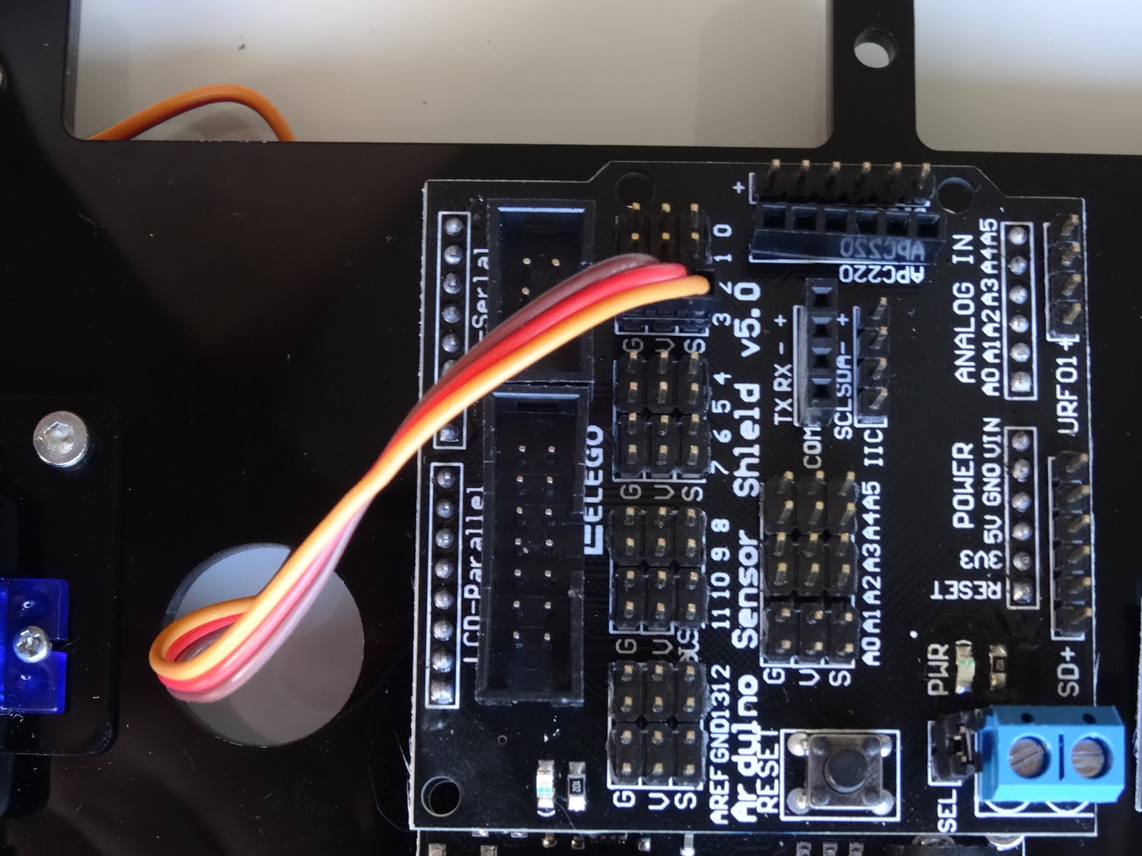
Connect the connector to the Digital 3 sensor connection point with the brown wire connected to the ground pin, and the yellow wire connected to the signal:

The Smart Car kit comes with 2 sets of Female-Female jumper cables. Short and long. I initially tried to use the short ones for the Ultrasonic Ranger, but they seem too short, so peal 4 wires from the long set of cables (In my case Yellow, Orange, Red and Brown):

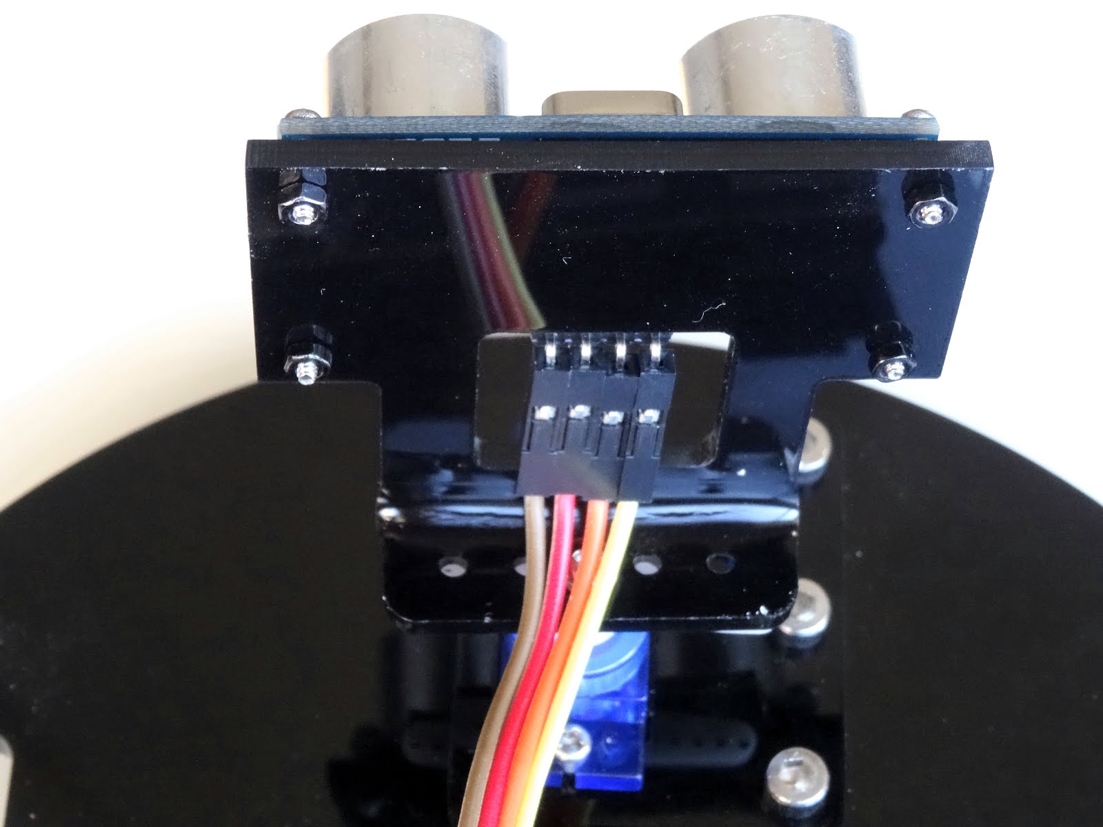
Connect the wires to the Ultrasonic ranger as shown on the picture - from the back left to right start with the Brown wire:
Connect the other end of the Brown wire (the one connected to the left pin from the back of the Ultrasonic Sensor) to the Ground pin of the A5 sensor connection points of the Sensor Shield:


Connect the Yellow Wire (the one connected to the right pin from the back of the Ultrasonic Sensor) to the Power pin of the A5 sensor connection points of the Sensor Shield:

Connect the Orange Wire (the one connected to the third pin from the left of the Ultrasonic Sensor) to the A5 Signal pin of the sensor connection points of the Sensor Shield:

Connect the last wire - Red Wire to the A4 Signal pin of the sensor connection points of the Sensor Shield:

Take the remaining short connection with white connector on one side, and black on the other, and connect the white connector to the Infrared Remote Sensor:

Connect the black connector of the wire to the connection points for pin 12 on the Sensor Shield, so the black wire is connected to ground, and the white to signal:


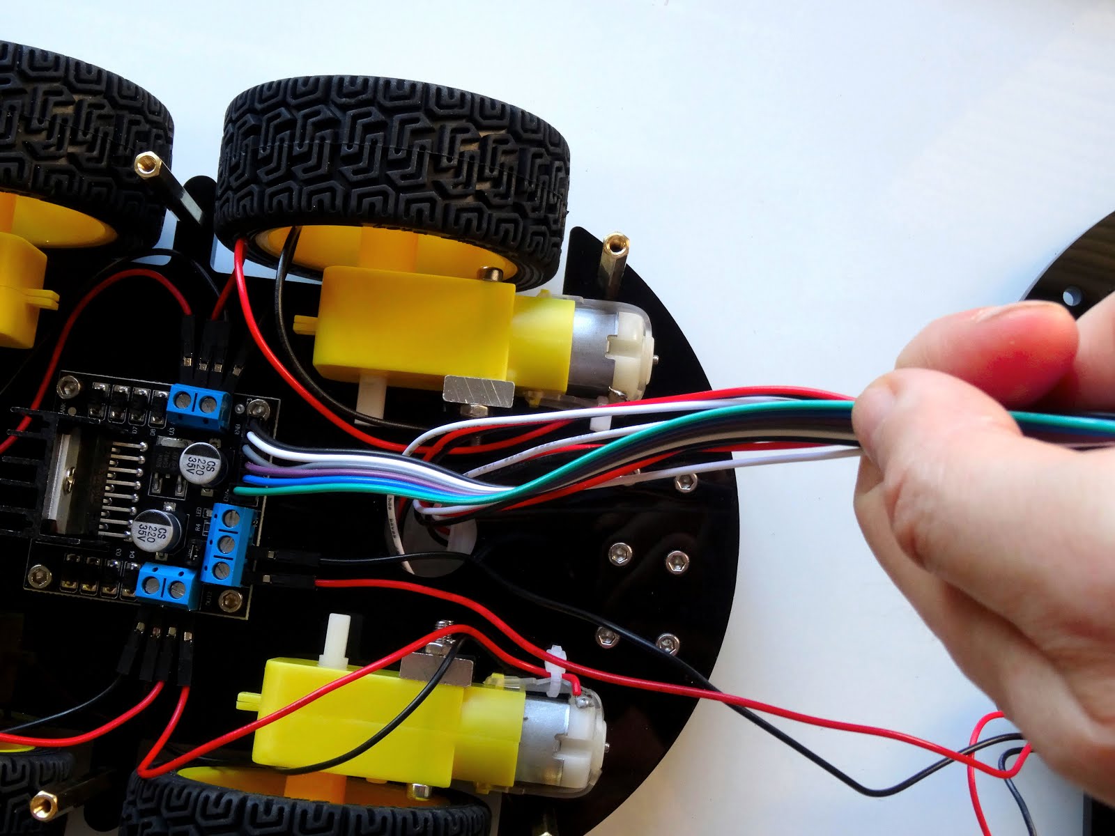
Split 6 long Female-Female jumper wires - in my case Green, Blue, Purple, Gray, White and Black:

Connect the wires to the L298N Motor Driver module control connector as shown on the pictures:


Now it is time to connect the 2 layers of the Chassis together. The Spacers and the Screws for them are packaged in 2 clearly labeled bags:

Take them out of the bags,

Flip the bottom layer of the Chassis - the one with the motors upside down and insert one of the screws from the bottom trough one of the corner holes, then screw the spacer on it from the top:


Do the same with the rest of the spacers:


Connect the power connector to the Arduino board:


Connect the Red Power wire from the power connector to the first connection point of the power connector of the L298N Motor Driver module:


Connect the Black Ground wire from the power connector to the second connection point of the power connector of the L298N Motor Driver module:


Grab all the cables that have unconnected ends together:
Push them through the big hole in the top Chassis layer from the bottom, so the unconnected ends appear on the top:


Place the top layer of the Chassis over the spacers, so the corner holes match, and insert and tighten screws through the holes.

I also inserted the power wires for the motor driver through the same big hole, to reduce clutter:


Connect the 6 wires from the motor shield to the signal pins 5 to 10 of the digital sensor pins, connecting the wire from the left pin (Green Wire) of the L298N Motor Driver module to pin 10, and the rest of the wires in order to the following pins until pin 5:


Connect the wire from the Right Line Following Sensor when looking from the back of the cart in normal upside position (The sensor on the opposite side of the power connector for the Arduino), to the points for pin 2 on the Sensor Shield, so the black wire is connected to ground, and the white to signal:


Connect the wire from the Center Line Following Sensor, to the points for pin 4 on the Sensor Shield, so the black wire is connected to ground, and the white to signal:

Connect the wire from the Left Line Following Sensor when looking from the back of the cart in normal upside position (The sensor on the opposite side of the power connector for the Arduino), to the points for pin 11 on the Sensor Shield, so the black wire is connected to ground, and the white to signal:


Here is the Smart Car robot with all the wires connected:


Optionally we can also install the Bluetooth module. The Sensor Shield has dedicated connector for it:


Be aware that when the Bluetooth module is installed, you will not be able to program the Arduino as it uses the same serial interface. You will need to remove the Bluetooth module every time you program the Arduino.


We can now also charge the rechargeable batteries. The Smart Car robot contains a battery charger. Make sure you use the included charger to charge the batteries, as otherwise you may damage them, or even cause fire!

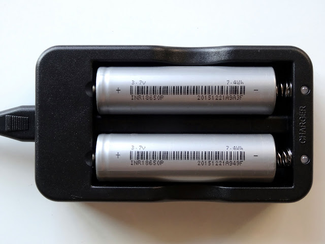
Unpack the batteries and the charger:

Insert the batteries into the charger making sure you match the + and - as labeled on the charger:

Connect the charger to power. The LEDs will light in red indicating charging the batteries:

Once the batteries are charged, the LEDs will turn greenish:

The Smart Car Robot is complete and ready to program. I will see to make some tutorials on programming it with Visuino in the coming days.
No comments:
Post a Comment